
Preamble
Welcome. Transferring information from my project book or computer to this page always seems to be a drawn out process. If you bear with me, I will be putting more stuff up online over the coming weeks (more so now that my rugby season came to an abrupt end). If you have any questions or corrections, feel free to send me an email, the link is at the bottom of the page. Cheers.
Upcoming updates include:
Thrust chamber assembly design write up should be polished off soon
Completion of the design for my raspberry pi controlled torch igniter, with dump cooling analysis and electronics etc
I have a bit of work on the pintle injector to chuck up, which should be interesting.
Introduction
The main objectives of Project Gravitas is to develop a liquid fuel bi-propellant rocket engine powered by methane and liquid oxygen (LOX).
The basic design requirements for the JKM-08 Engine are given below:
Propellants shall be liquid oxygen and liquid methane
Thrust requirement of 5kN
Thrust chamber weight shall be less than 20 kg
The thrust chamber will be cooled by both regenerative and film cooling
Current LOX/Methane Engines
Traditionally, high performance rocket engines have used LOX and hydrogen or LOX and kerosene, as such methane has not yet been used in a commercial launch vehicle. However, several LOX/Methane engines have been built or are currently under development. XCOR along with Alliant Techsystems Inc. (ATK) built a 33 kN LOX/Methane regeneratively cooled engine as part of the NASA's Exploration Technology Development Program ( Figure 1.a ). This engine is pressure fed, and was designed to be self pressurizing, thus has no associated pumps or propellant tank pressurization system. To enhance the engine life, liquid methane passed through coolant channels machined into the combustion chamber. This work identified flow instabilities in the coolant channels with methane at subcritical conditions. A Purdue University student team has designed, built and tested a liquid LOX/Methane thrust chamber as part of NASA's Project Morpheus (Figure 1.b). The thrust chamber was designed to be throttled between 5,800 N and 18,700 N at a chamber pressure of 1.72 MPa. The chamber diameter was 192.7 mm with a characteristic length of 50. The combustor was developed to collect data on cooling requirements for a flight weight engine, current testing is focusing on the temperature profile of the thrust chamber wall. As part of NASA's Propulsion and Cryogenics Advanced Development Project, Aerojet developed a LOX/Methane reaction engine based off their previous LOX/Ethanol engines, and also a 24,500 N main engine for lunar lander assents. The major issues to arise from current LOX/Methane engine development is injector design, reliable ignition and the lack of data on the regenerative coolant characteristics of Methane.

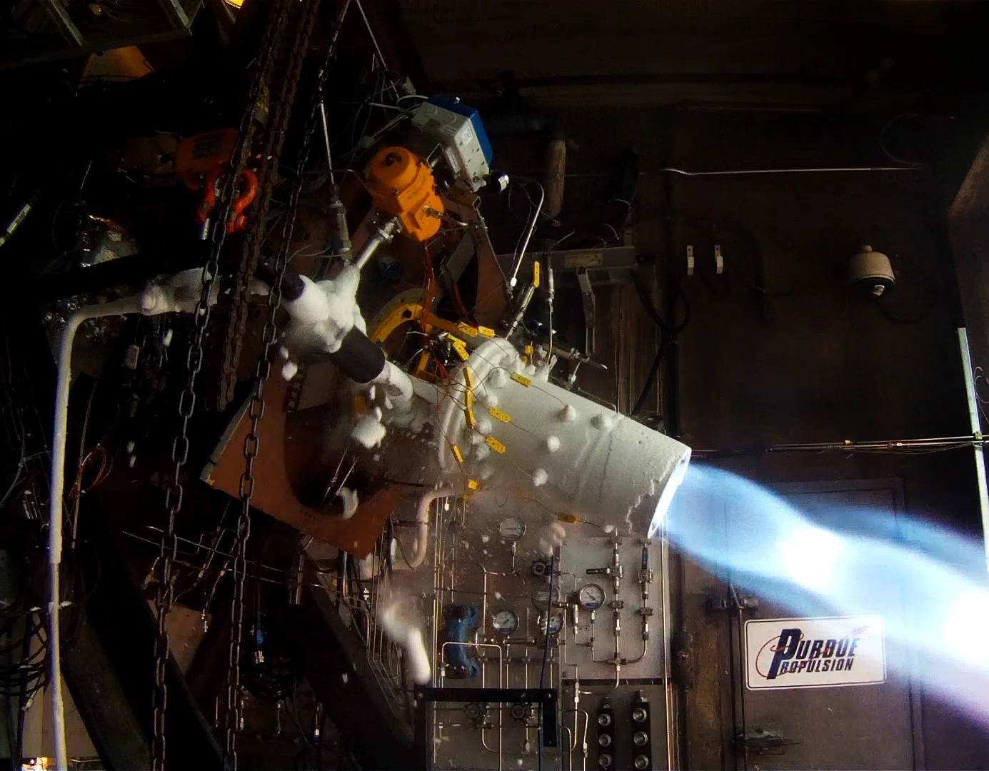


Figure 1. a) XCOR test firing of a 7,500 pound-thrust LOX/methane engine b) Purdue students designed an built a 17kN LOX/CH4 combustion chamber as part of NASA's Project Morpheus. c) Aerojet 100-lbf LOX/LCH4 reaction control engine in test at NASA GRC. d) Firefly Space Systems was developing a LOX/methane engine for a light satellite launch vehicle.
Engine Specifications
From the basic design requirements we have the following engine specifications:
| Parameter | Specification value |
|---|---|
| Thrust | > 5 kN |
| Chamber pressure | 1 - 6 MPa |
| Specific Impulse | > 250 s |
| Mixture ratio | 2.5 - 3.6 |
| Mass | Minimize < 25 kg |
| Propellent Feed | Pressure Fed |
| Burn Time | > 15 s |
NOMENCLATURE
\(\dot{m}\) = Mass Flow Rate
F = Thrust
R = Gas Constant
k = Specific Heat Ratio
\(T_1\) = Chamber Temperature
ε = Nozzle Area Ratio
\(I_{sp}\) = Specific Impulse
\(A_t\) = Throat Area
\(A_2\) = Nozzle Exit Area
\(P_1\) = Chamber Pressure
\(P_2\) = Nozzle Exit Pressure
\(P_3\) = Ambient Pressure
Subscripts
1 - Chamber
t - Throat
2 - Nozzle Exit
Propellant
In recent times liquid oxygen-liquid methane (LO2/LCH4) has been considered as a potential “green” propellant alternative for future exploration missions. In addition, a fairly high Isp can be achieved using methane, and its density is desirable for easy storage in small tanks, compared to what would be required for liquid hydrogen. Methane is also abundant in the outer solar system. It can be harvested from Mars, Titan, Jupiter, and many other planets and moons. With fuel waiting at the destination, a rocket leaving Earth wouldn't have to carry so much propellant, reducing the cost of a mission.
isp variation with chamber pressure
Figure 2 - Variation of vacuum specific impulse with chamber pressure
Chemical Equilibrium with Applications (CEA) Analysis
In order to begin the study of the performance of this engine, it is necessary to choose the O/F mixture ratio that the engine will operate at. The O/F ratio for the design chamber conditions was determined by a nested analysis in the NASA computer program CEA (Chemical Equilibrium with Applications). CEA can be used to find the thermodynamic properties and theoretical performance of the rocket engine, numbers that are needed to design the thrust chamber assembly. The near optimum value of O/F = 2.95 was eventually chosen. This value corresponds to the maximum engine specific impulse at sea level.
Figure 3 - Variation of sea level specific impulse with O/F ratio at a chamber pressure of 2 MPa
Engine Performance loss due to Film cooling
Because film cooling is being used to reduce heat transfer to the chamber wall , we must determine the negative affect the fuel coolant stream has on the rocket engines performance. For this rocket engine, the mass flow rate of the fuel coolant is set at \(\phi\) = 0.3 of the total methane flow into the combustion chamber. This value is inline with other LOX/Methane engines that utilize film cooling, such as Project Morpheus or Purdue's test engine.
Treating the fuel as a separate stream from the main core chamber flow for analysis purposes, and by also neglecting mixing, the following equation can be used to find the effective Isp
This mass averaging approach requires a value for the fuel film Isp. To find this number by running CEA, the effective O/F ratio of the wall region must be found.
To estimate the O/F value at the wall, we could use the following equations. The first approach is to add the mass flow of the fuel film to the core fuel mass flow when calculating the O/F ratio as follows:
The second method uses NASA's Analytical Model for Gas Film Cooling to estimate the wall O/F value:
were η is the film coolant effectiveness based on total enthalpy. Plugging in values to the Analytical Model for Gas Film Cooling, we have the following wall O/F
Now that the wall oxidizer fuel ratio has been found, we can run CEA to find the film coolants contribution to the engine performance. The CEA output for the fuel film can be seen in Table 4. Finally, we can rewrite Equation 1 in terms of the mass fraction of fuel coolant (Equation 5)
Propellant mass flow rates
At this point we have the required information to calculate mass flow of our propellants and coolant. The mass flow of the coolant film and the core gas flow in terms of the total fuel flow are
with the total mass flow of propellants
By plugging Equations 7, 8 and 9 into Equation 5, we can solve for the film coolant mass fraction which is needed to calculate the Isp.
Now we can calculate the total propellant mass flow by solving Equation 6 and using the Isp with the desired thrust to find the propellant flow rate.
To calculate the oxidizer, fuel and coolant mass flow rate, we need the effective O/F ratio
Now we can break down the total propellant flow
To this point we have the effective Isp and mixture ratio, as well as our flow rates into the chamber
| Parameter | Specification value |
|---|---|
| Isp | 254.2 s |
| Oxidizer Flow Rate | 1.38 kg/s |
| Fuel Flow Rate | 0.63 kg/s |
| Mixture ratio | 2.2 |
Thrust Chamber Assembly
Nozzle
Basic Sizing - One dimensional nozzle flow
An ideal rocket nozzle is permitted by making several simplifying assumptions that allow basic thermodynamic relations to be expressed as basic mathematical relations. These assumptions lead to quasi-one-dimensional nozzle flow, which is an idealization of 3-dimensional flow in a nozzle, and allow us to perform preliminary design tasks which can then be corrected through 2 and 3 dimensional analysis. These assumptions typically give a good estimate of nozzle performance, with final measured values within 1 - 6 % of ideal values [ref]. The following table gives gives the values calculated by the program CEA used in the quasi-one-dimensional nozzle calculations.
Table 2 - Parameter values as calculated in CEA with a reaction efficiency of 0.9782 and nozzle efficiency of 0.9767
| Parameter | Specification value |
|---|---|
| Thrust | 5 kN |
| Chamber pressure | 2 MPa |
| Specific Impulse (sea level) | 254.2 s |
| Mixture ratio | 2.2 |
| Design Pressure | 101,325 Pa |
| C* | 1752.0 m/s |
To find the throat area, we can use the following expression:
were \(A_t\) is the throat area, \(C*\) is the characteristic velocity and \(P_c\) is the pressures at the chamber. Calculating the effective C* of the engine with
the throat diameter is
By definition an ideal nozzle expands the throat flow isentropically and produces a parallel uniform exit flow at a prescribed exit Mach number, \(M_2\) , or ε. The expansion ratio for such a nozzle is given by
And thus we have an exit area of
UPSTREAM CONTOUR
DOWNSTREAM CONTOUR
Conical Nozzle
The conical nozzle is the basic form of the diverging nozzle and is used when performance and length are not critical and ease of fabrication (and low cost) is desired. In applications with low area ratios, conical nozzles can be used with no measurable loss in performance. The 15° conical nozzle is used as the reference length when evaluating other nozzle contours.

Thrust optimized PARABOLA (Rao nozzle)
For engineering purposes an approximation to the optimum thrust contour is close enough, comparative losses between an optimal and approximated Rao nozzle have been shown to be small. The optimum thrust nozzle contour can be closely approximated by a canted parabola.

The parabola has to fit the maximum wall inclination \(\theta_M\) in the throat region and the wall inclination \(\theta_E\) at the nozzle exit. The following equation yields the necessary wall slope \(\theta_E\)
In his paper, Rao constructs the parabola through graphical means.
were \(b_{i,n}\)are known as Bernstein polynomials of degree n and the points \(\mathbf{P}_i\) are called control points for the Bézier curve. In the case of the TOP nozzle, the degree of the polynomials is 2 so
and the equation for the Bézier portion of the TOP nozzle is as follows
From Rao’s paper, the control points, \(P_i\), are \(\mathbf{M}\), \(\mathbf{Q}\) and \(\mathbf{E}\). \(\mathbf{M}\) is the point were the initial prescribed curve ends and the Bézier curve begins, \(\mathbf{E}\) is the end point of the nozzle and \(\mathbf{Q}\) is the intersection for of the lines passing through \(\mathbf{M}\) and \(\mathbf{E}\) with incline \(\theta_M\) and \(\theta_E\) respectively.
To find the coordinates of \(\mathbf{Q}\), we need the equations of the lines through \(\mathbf{M}\) and \(\mathbf{E}\). The equation of a straight line is
were \(m\) is the slope and \(n\) is the y-intercept. The slope \(m\) is related to the angle of incline by \(m = \tan(\theta)\) and the y-intercept is found by inputting known x and y values and solving for n:
Now we have the following equations
and we can equate them to find the x coordinate of intersection, \(\mathbf{Q}\)
\(Q_x\) can then be substituted back into either line equation to find \(Q_y\).
Now that the control points are defined, the equation of the parabola portion of the nozzle is
Ideal CONTOUR (method of CHARACTERISTICS - Minimum Length Nozzle)
Method of Characteristics - Minimum Length Nozzle code
Thrust Chamber
The thrust chamber consists of the volume between the injector face plate and the throat where the combustion process takes place. In order to ensure that combustion stability is achieved, the thrust chamber must be designed such that the length is long enough to ensure proper mixing and combustion of the propellants. If the length is too short and the propellants exit the chamber without mixing and combusting, performance is lost.
Calculating Chamber Length With L*
Calculating Chamber Length Considering propellant vaporization - One Dimensional Idealization
Regenerative cooling
Injector
The liquid rocket engine injector is one of the most complex components of the engine. Injector design consists of a fine balance between combustion stability and efficiency, manufacturing complexity, and cost.
Pintle injectors have several advantages over other methods of injectors. A major advantage of pintle injectors is their inherent combustion stability, there has never been a case of combustion instability reported with pintle type injectors. This eliminates the need for complex baffles and acoustic measures on the injector face. Since as few as five parts can be used for the injector assembly, the manufacturing and assembly of the injector can also be quite simple compared to multi-element injectors.
Pintle Injector Design
Figure x shows some of the major design elements of the pintle injector. The most important deign variable is the Total Momentum Ratio (TMR), which is the annular/radial stream momentum ratio. For optimal performance the TMR value should be around 1, the pintle injector in the lunar lander module had a TMR of 1.04. Another important ratio is between the chamber diameter and the pintle diameter. Typically this falls between 3 and 5. The skip length (Ls) is the distance the annular flow travels before it impacts on the radial flow slots. The ratios between the skip length and the pintle diameter is normally around 1.

\(L_s\) = Skip Length Gap = Fuel Orifice \(D_{pri}\) = Primary Pintle Holes
\(R_p\) = Pintle Radius \(R_c\) = Thrust Chamber Radius \(D_{sec}\) = Secondary Pintle Holes
To prevent combustion instabilities, the pressure drop over the injector of should be greater than 15% of the combustion chamber pressure. To err on the side of cation, the pressure drop over the injector will be set to a conservative 0.2 Pc.
Methane-Oxygen torch Igniter
To meet requirements of this project, the igniter has to be at the same time reliable, simple and cheap, suitable for the full size thrust chamber but easy to adapt for the installation on small-scale chambers. With these requirements in mind, the choice has been made to develop a torch igniter. Note that many modern restartable rocket engines use either a torch igniter or a hypergolic igniter.
The basic operation of a torch igniters is the combustion of a bipropellant mixture, which is obtained from the main propellant tanks or from a separate feed system. Here, gaseous methane and oxygen at ambient temperature are introduced into the torch combustion chamber through two ports and ignited using a spark plug. The torch flame produced burns at a temperature of approximately 3000 K, which vaporizes and ignites the main chamber propellants. A large benefit of the torch igniter is to provide experience that will be relevant throughout this project (such as chamber design, test stand construction, data acquisition etc.), because a torch igniter is, in its most basic form, a small rocket engine.
The difficulty with igniter design is understanding the exact ignition requirements of a rocket engine. When the igniter is ignited, it must provide sufficient thermal power to ignite the liquid oxygen and methane in the combustion chamber. One approach to finding the required ignition energy is to calculate the energy required to raise the propellant temperature to Tig, the spontaneous ignition (autoignition) temperature of the propellant combination.
Minimum Ignition Energy Requirement
When calculating the minimum ignition energy using the autoignition temperature method, the full propellant flow into the chamber is not typically considered, rather a fraction of this flow (such as the flow through the inner ring of an injector). In this case, 10% of the initial flow rate will be evaluated. To find the required energy, we consider the enthalpy change when the temperature of the propellants is increased. Also, the phase change of the propellants must be accounted for, as both oxygen and methane enter the combustion chamber in liquid form. Thus the Enthalpy of Vaporization must be included in the calculation (Δhvap). We have the following equation for the energy required to raise the temperature of the propellants:
For the change in enthalpy associated with the temperature rise, ΔH, the following equation can be substituted
Cp for both oxygen and methane must be integrated over the range of temperatures we are interested in as there is too much variance in the heat capacity values to be considered constant. To evaluate gas phase Cp, we use the Heat Capacity (Shomate Equation) from the NIST Webbook :
where t = temperature(K) / 1000 and Cp = J/mol*K. The constants A, B, C, D and E for both oxygen and methane are found on their NIST thermochemistry data pages (Oxygen, Methane). The liquid phases heat capacity for both fuels is also found in the NIST Webbook, in the fluid property tables (Methane). Solving the following equation
integrating for both Cp terms numerically, we get a value of
for the required power input to successfully start the engine.
From the energy required of an igniter for LOx/CH4 combustion, the sizing of the igniter can be completed. As will be covered in more detail further on, the igniter core O/F will be manipulated to reduce the heat flux through the igniter chamber wall. For the sake of this exercise we will assume the ratio of gaseous oxygen and methane at combustion is 3.05.
Igniter Chamber design
| Parameter | Specification value |
|---|---|
| Torch Igniter Power | 150 kW |
| Mass Flow Rate | 0.033 kg/s |
| Core Mixture ratio | 24 |
| Overall Mixture ratio | 3.05 |
| Energy per Spark | 35mJ |
| Spark Rate | 100 Hz |
| Nominal Firing Time | 1.5 s |
As mentioned, a spark igniter is similar in principle to a small rocket engine. Gaseous propellants are fed to small chamber, where the propellant are ignited by an electrical spark. The flow is choked through the throat of the igniter into the nozzle, from which the combustion gases flow into the main combustion chamber. Because of the heat flux into the igniter wall, cooling is required to increase the life of the igniter. A method of regenerative/dump cooling is employed to keep the wall temperature below the material failure point. The methane flow is split with a mass flow of kg/sec entering the igniter combustion chamber and kg/sec flowing down along the outside of the torch combustion chamber and nozzle as the coolant fluid. The gaseous oxygen flow is kg/sec, which makes the combustion chamber O/F equal to 24. This was chosen to create a combustion temperature of approximately 2000 K . At the exit of the torch nozzle, the gaseous methane coolant mixes with the products of combustion and the resulting O/F ratio is 3.05.
Regenerative/dump cooling
Ignition system Electronics
A system such as this requires high voltage electronics, which generate the spark to ignite the gaseous mixture in the chamber.
Igniter test Stand
PROPELLANT tank pressurization system
References
NASA Space Vehicle Design Criteria (Chemical Propulsion), ’’Liquid Rocket Engine Nozzles’’, SP-8120, July 1976
Frey, H. M. , Nickerson G. R. “TDK –Two Dimensional Kinetic Reference Program”, SEA Inc. NAS8 36863,1989.
Rao G. V. R. , “ Exhaust Nozzle Contour for Optimum Thrust” , Jet Propulsion , Vol. 28, No. 6, 1958
Huzel D. K., Huang D. H., “Modern Engineering for Design of Liquid Propellant Rocket Engines”, Revised Edition. AIAA Progress in Astronautics and Aeronautics, Vol. 147. Washington, DC: AIAA 1992.
Rao G. V. R. , “ Approximation of Optimum Thrust Nozzle Contour” , ARS Journal , Vol. 30, No. 6, p. 561, 1960.